1.1 THE GENERATION OF THRUST BY A ROCKET ENGINE
The function of a chemical rocket engine system is to generate thrust through combustion; i.e., release of thermal energy derived from the chemical energy of the propellants. The generated force (pressure) imparts a momentum to the combustion products. In accordance with the basic laws of motion, a momentum in the opposite direction is also imparted to the vehicle. In practice, high temperature, high-pressure gases are produced in combustion chambers through chemical reactions of either solid or liquid propellants. These gases are ejected through a nozzle at high velocity. The operation of a rocket engine system is independent of its environment except for slight effects on performance caused by ambient air pressure. The rocket or, in a more general sense, the "reaction motor" presently is the only practical device able to propel a vehicle in space.
Let us examine briefly the process of thrust generation and summarize the most frequently used laws and formulae needed to design the shape and to predict the behavior of a rocket engine. These laws are mere adaptations of basis physical laws. We know that
Force equals mass times acceleration. We also know that the velocity increase experienced by the accelerated mass, during the time the force is imparted, is
Combining these two fundamental relations, we obtain
This expression, known as the momentum theorem, is the basic thrust equation for rocket engines. When applied to rocket engines, the term for mass. , and the term for velocity, , may apply either to the vehicle or to the ejected gases. The products of and , in opposite directions, must be equal, as prescribed by the law of action and reaction. This condition exists even in a "tiedown" static rocket firing. In this case, however, the "vehicle mass" (the earth) is so large that reaction effects are undetectable.
The vehicle designer is primarily interested in the utilization of the engine thrust available for the acceleration of the vehicle, which at any point of the trajectory may be expressed as
The vehicle designer uses this equation for vehicle design and trajectory calculations, properly considering that thrust and vehicle mass change during flight.
In contrast, the engine designer and builder is primarily concerned with the generation of thrust. His attention, therefore, is focused on the efficient conversion of the chemical energy of the propellants into thermal energy, and thus into kinetic energy of the gaseous combustion products. His particular concern is to do this in the most efficient way. For the designer, the basic equation (1-3) may be rewritten as
where is the mass flow rate of the gases, and is their velocity at the nozzle exit. Even in this simple form, it becomes clear that, for a given mass flow rate, thrust will increase with increased gas velocities obtained.
It should be remembered that the vehicle, in particular the thrust chamber of the engine, is also subject to the pressure environment, which is a function of altitude. Equation (1-3b) states that if a mass is flowing out of a container, the sum of all internal and external forces acting on all surfaces of this container is equal to the total momentum flowing out of the surface. The liquid propellant rocket thrust chamber, with the inclusion of the exit plane, is such a container (fig. 1-1).
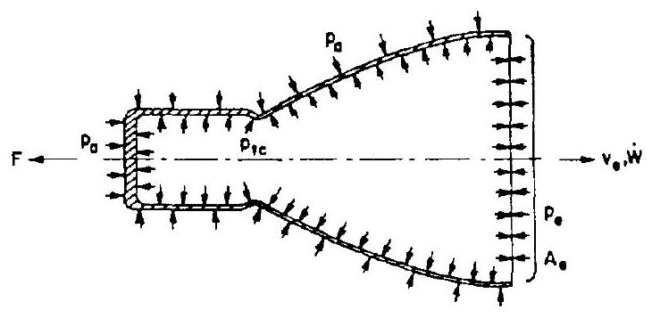 Figure 1-1
Let us first assume that the chamber is operated at an ambient pressure (high-altitude condition). Then, the net force acting on the gas in the chamber is the sum of the reactions from the chamber walls and of the reaction of the absolute gas pressure at the exit. These two reaction forces are opposed (fig. 1-1). According to the momentum theorem, the net force on the gas must be equal to the momentum flux out of the chamber:
The integral describes that force (lb) which acts on the thrust chamber and thus on the vehicle. We can write:
or
where or psia) is the static absolute gas pressure in the exit plane . The equation assumes that the injection flow velocity of the propellants can be neglected and that the flow of gases through the exit plane is onedimensional; i.e., that all molecules of the gas move on parallel lines. The expression is often referred to as the momentum thrust, and as the pressure thrust. The pressure thrust is not a desirable form of thrust generation in rocketry. The presence of the term indicates that not all of the pressure forces available have been converted into gas kinetic energy inside the chamber nozzle. In other words, a portion of the gas pressure generated by the release of chemical energy has not been used for the generation of gas momentum. It is the specific function of the thrust chamber nozzle to convert, at maximum efficiency, the available chamber pressure into gas momentum, and thus obtain maximum thrust for a given propellant flow rate.
We now assume that the rocket is operated at a finite ambient pressure (lowaltitude condition). The resulting pressure forces acting on the outside of the chamber walls have no effect on the gas on the inside. However, these pressure forces cancel part of the pressure thrust by an amount . Since gases are flowing with supersonic velocity in the exit plane , the ambient pressure does not have access to it. The ambient pressure thus creates a net unbalanced force onto the projected thrust chamber area (opposing the thrust) of magnitude . Including this term in equation (1-5), the general rocket thrust equation is obtained:
The following model may extend the understanding of the nature of the terms which compose equation (1-6). Let us assume we have a movable cylinder (representing the thrust chamber and vehicle mass), a spring (representing gas pressure), a piston (representing the gas mass), and a stationary rack (representing ambient conditions) (fig. 1-2).
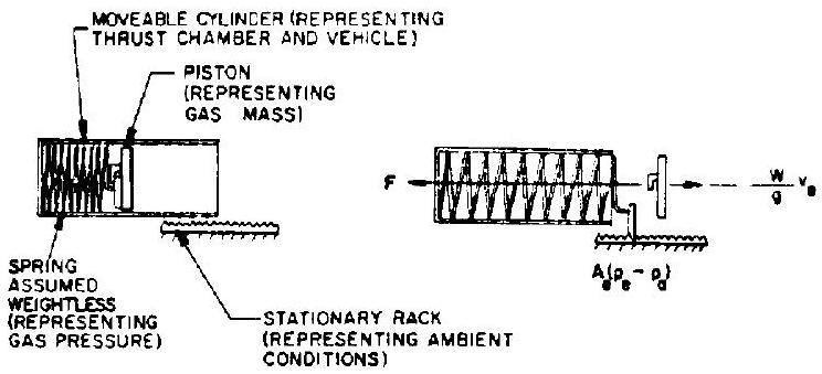 Figure 1-2
The spring is so made that its end slips sideways upon reaching the end of the cylinder and engages the stationary rack. The cylinder is suspended in a suitable manner to move freely.
When releasing the spring force (" "), the "gas" is expelled to the rear. If, upon reaching the chamber exit, some spring force remains, the spring engages the rack and continues to act upon the cylinder, but ceases to act upon the "gas." We find that the model works for all cases: underexpanded (as assumed above, where spring free length is longer than cylinder length); overexpanded (spring free length is less than cylinder length and the spring force is exhausted prior to the "gas" reaching the exit, the "gas" therefore being subject to deceleration within the cylinder); and ideal expansion (where spring free length equals cylinder length).
The model can also illustrate the case of the overexpanded nozzle without jet separation, which will be further explained below. This situation is equivalent to that of the inertia of piston ("gas") and spring pulling the spring beyond its null point. The negative-loaded spring, in engaging the rack ("ambient"), will pull the cylinder backward.
Equation (1-6) is often expressed as
Where is defined as the effective exhaust velocity ( ) and comprises
The effective exhaust velocity is not the actual gas velocity except when where becomes equal to . As explained with equation (1-6), the presence of a term ( ) indicates that optimum has not been obtained.
Sample Calculation (1-1)
The following data are given for a liquid propellant rocket engine: thrust, at sea level; propellant consumption rate, ; thrust chamber exit area, in ; gas exit static pressure, ; ambient pressure, (sea level); gravitational constant, .
From what we have just learned, we will determine (a) gas exhaust velocity, (b) engine thrust in space, and (c) the effective exhaust velocities at sea level and in space.
Solution
(a) From equation (1-6) the gas exhaust velocity
Our calculation assumes a nozzle somewhat too long for sea-level conditions, as indicated by the fact that is smaller than ; a pressure "undershoot" and an exhaust velocity "overshoot" occurred. If no jet separation occurred, i.e., if the nozzle remained "filled" to the exit plane, the calculation is valid. The "penalty" of incorrect nozzle length simply appears as the negative thrust term . If jet separation does occur within the nozzle, or if it is combined with decelerating shock waves, the situation becomes considerably more complicated and requires elaborate mathematical treatment. However, there should be no concern at this point. (b) From equation (1-6), we know that the difference in thrust between space and sea level is . Since the nozzle selected was too long at sea level, this thrust increase during rocket ascent will be obtained in two distinct steps. First, by reduction of the negative thrust term to zero. This will occur when ; that is, when the rising vehicle reaches an altitude where , in our specific case. As we have learned, this represents ideal expansion. As the vehicle continues to ascend farther and eventually reaches "empty space" where , the increase of the positive term raises the thrust level farther. The combined effect of the two phases, however, is simply the elimination of , provided the nozzle is filled at all times.
Thus, we obtain engine thrust in space:
(c) From equation (1-8) the effective exhaust velocity at sea level results
and in space